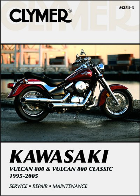
This Haynes 2457 repair manual covers 1985-2006 Kawasaki Vulcan motorcycles, including:
- Kawasaki Vulcan 700, 1985
- Kawasaki Vulcan 750, 1985-2006
- Kawasaki Vulcan 800, 1995-2005
- Kawasaki Vulcan 800 Classic, 1996-2002
- Kawasaki Vulcan 800 Drifter, 1999-2006
Book Excerpt: 1985-2006 Kawasaki Vulcan, Classic, Drifter Repair Manual COOLING SYSTEM
COOLING FAN AND THERMOSTATIC SWITCH - CHECK AND REPLACEMENT CHECK
- If the engine is overheating and the cooling fan isn't coming on, first check the fuses (see Chapter 9). If the fuse is blown, check the fan circuit for a short to ground (see the Wiring diagrams at the end of this book). If the fuses are all good, disconnect the fan electrical connector (see illustration 11.a or 1.1b). Using two jumper wires, apply battery voltage to the terminals in the fan motor side of the electrical connector. If the fan doesn't work, replace the motor.
- If the fan does come on, the problem lies in the thermostatic fan switch, the junction block, or the wiring that connects the components. Remove the jumper wires and reconnect the electrical connector to the fan.
- If you're working on a Vulcan 700/750 model (with a single-wire fan switch harness), disconnect the electrical connector from the fan switch, attach a jumper wire to the harness side of the connector and ground the other end of the jumper wire. If the fan comes on, the circuit to the motor is good, and the thermostatic fan switch is defective.
- If you're working on a Vulcan 800 model (with a double-wire fan switch connector), disconnect the connector. Connect the terminals in the harness side of the connector together with a jumper wire. If the fan comes on, the circuit to the motor is good and the switch is defective.
- If you're working on Vulcan 700/750 model and the fan still doesn't work, trace the fan relay (located under the seat on the junction box - use its wire colors for identification) and place your hand on it. Repeatedly touch the jumper wire to ground as detailed in Step 3 - if you feel and hear a clicking inside the relay, the relay is good and the fault must lie in the wiring from the relay to the fan motor.
BRAKES, WHEELS AND TIRES
MASTER CYLINDER: REMOVAL, OVERHAUL AND INSTALLATION
- If the master cylinder is leaking fluid, or if the lever does not produce a firm feel when the brake is applied, and bleeding the brakes does not help, master cylinder overhaul is recommended. Before disassembling the master cylinder, read through the entire procedure and make sure that you have the correct rebuilt kit. Also, you will need some new, clean brake fluid of the recommended type, some clean rags and internal snap-ring pliers. Caution: To prevent damage to the paint from spilled brake fluid, always cover the fuel tank when working on the master cylinder.
- Caution: Disassembly, overhaul and reassembly of the brake master cylinder must be done in a spotlessly clean work area to avoid contamination and possible failure of the brake hydraulic system components.
Subject: 1985, 1986, 1987, 1988, 1989, 1990, 1991, 1992, 1993, 1994, 1995, 1996, 1997, 1998, 1999, 2000, 2001, 2002, 2003, 2004, 2005, 2006 Kawasaki Vulcan 700, 750, 800 service, maintenance, repair. ISBN-10: 1620922894 | ISBN-13: 9781620922897 | Haynes 2457
TABLE of CONTENTS:
LIVING WITH YOUR KAWASAKI VULCAN
Introduction
- Identification numbers
- Buying parts
- Engine/transmission oil level check
- Brake fluid level checks
- Suspension, steering and final drive checks
- Tire checks
- Specifications
- Maintenance schedule
- Component locations
- Maintenance procedures
- Engine, clutch and transmission
- Cooling system
- Fuel and exhaust systems
- Ignition system
- Steering
- Suspension
- Final drive
- Wheels
- Brakes
- Tires
- Frame and bodywork
- Tools and workshop tips
- Storage
- Troubleshooting


