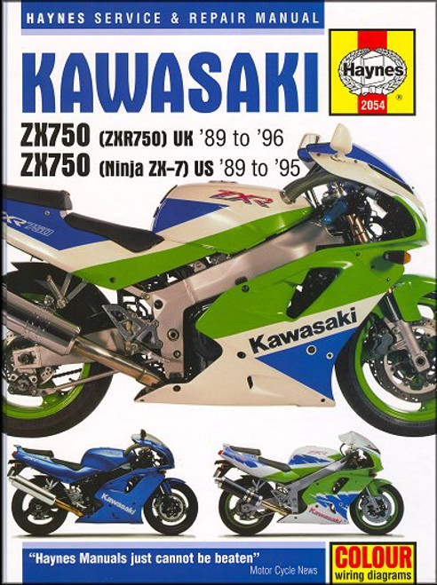
The 1989-1996 Kawasaki Ninja ZX7, ZX750, ZXR750 sportbike repair manual by Haynes covers:
U.S. Models:
- Kawasaki ZX750H (Ninja ZX-7), 1989-1990
- Kawasaki ZX750J (Ninja ZX-7), 1991-1992
- Kawasaki ZX750L (Ninja ZX-7), 1993-1995
- Kawasaki ZX750K (Ninja ZX-7), 1991-1992
- Kawasaki ZX750M (Ninja ZX-7), 1993-1994
U.K. Models:
- Kawasaki ZX750H (ZXR750), 1989-1990
- Kawasaki ZX750J (ZXR750), 1991-1992
- Kawasaki ZX750L (ZXR750), 1993-1996
- Kawasaki ZX750K (ZXR750R), 1991-1992
- Kawasaki ZX750M (ZXR750R), 1993-1994
The Kawasaki ZX750F (Ninja 750R or GPX750 R) 1985-1997, is covered in Haynes Manual #1780.
Note: this manual DOES NOT cover the ZX750P (Ninja ZX-7R) or ZX750N (Ninja ZX-7RR) introduced in 1996.
Book Excerpt: 1989-1996 Kawasaki Ninja ZX7, ZX750, ZXR750 Repair Manual STEERING, SUSPENSION AND FINAL DRIVE
STEERING STEM BEARINGS | REMOVAL, INSPECTION, INSTALLATION REMOVAL
- If the steering head bearing check and adjustment (see Chapter1) foes not remedy excessive play or roughness in the steering head bearings, the entire front end must be disassembled and the bearings and races replaced with new ones. H MODELS
- Remove the fuel tank (see Chapter 4).
- Remove the upper and lower fairings (see Chapter 8).
J, K, L AND M MODELS- Remove the upper fairing (see Chapter 8).
- Disconnect the ignition main (key) switch electrical connector (see Chapter 9 if necessary).
ALL MODELS- Unbolt the brake hose union from the lower triple clamp. There is no need to disconnect the hydraulic hoses, but make sure no strain is placed on them.
- Remove the front forks (see Section 4).
- Refer to Section 2 and lift off the upper triple clamp.
- Remove the lock washer from the stem locknut (see illustration). Using a spanner wrench (C-spanner), remove the stem locknut and bearing cover (see illustrations) while supporting the steering head from the bottom.
- Remove the steering stem and lower triple clamp assembly. If its stuck, gently tap on the top of the steering stem with a plastic mallet or a hammer or a wood block.
- Remove the upper bearing (see illustration).
FAIRING, BODYWORK AND FRAME
SEATS | REMOVAL AND INSTALLATIONH MODELS
- Insert the ignition key in the seat lock. Press down on the rear seat, turn the key clockwise and lift the rear seat. Together with its cover.
- Remove the two mounting bolts at the rear edge of the front seat, then pull it toward the rear of the motorcycle to remove it.
J AND L MODELS- Insert the ignition key in the seat lock. Press down on the rear seat, turn the key counter clockwise (anti-clockwise) and lift out the rear seat.
- Pull the seat latch lever to the rear (see illustration), then lift the rear end of the front seat and pull it backward to remove it.
K AND M MODELS- Insert the ignition key in the seat lock. Turn the key clockwise and remove the pad at the back of the seat.
- Reach inside the rear bodywork, pull the seat latch forward and lift the seat out.
ALL MODELS- Installation is the reversal of the removal steps. Make sure the seat lock or latch engages securely.
Subject: 1989, 1990, 1991, 1992, 1993, 1994, 1995, 1996 Kawasaki Ninja ZX7, ZX750, ZXR750 service, maintenance, repair. ISBN-10: 1785212729| ISBN-13: 9781785212727 | Haynes 2054
TABLE of CONTENTS:
KAWASAKI ZX750 MAINTENANCE
Introduction
- Buying parts
- Engine oil level
- Brake fluid levels
- Tires
- Routine maintenance and servicing
- Specifications
- Maintenance schedule
- Component locations
- Maintenance procedures
- Engine, clutch and transmission
- Cooling system
- Fuel and exhaust systems
- Ignition system
- Steering
- Suspension
- Final drive
- Wheels
- Brakes
- Tires
- Frame and bodywork


