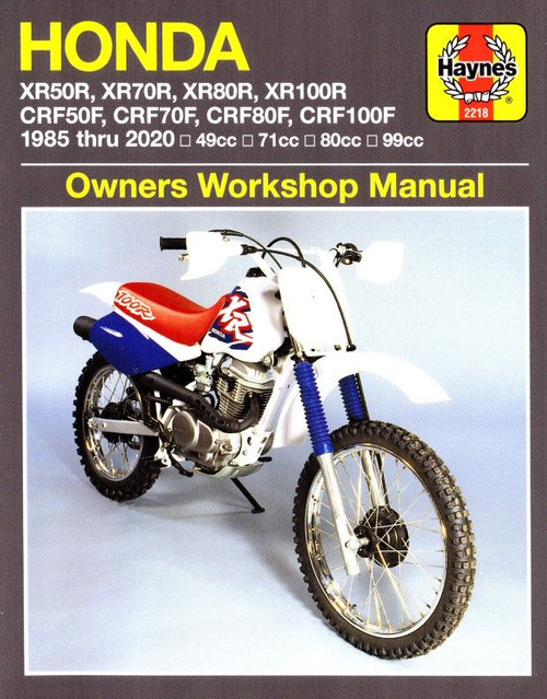
The 1997-2016 Honda XR50R, CRF50F, XR70R, CRF70F repair manual by Clymer covers:
- Honda XR50R 2000-2003
- Honda CRF50F 2004-2016
- Honda XR70R 1997-2003
- Honda CRF70F 2004-2012
Book Excerpt: 1997-2016 Honda XR50R, CRF50F, XR70R, CRF70F Repair Manual ENGINE LOWER END
CRANKCASE AND CRANKSHAFT INSPECTION Handle the crankshaft carefully when performing the following cleaning and inspection procedures. Individual crankshaft components are not available separately. If the crankshaft is excessively worn or damaged, or if any measurement is out of specification, replace the crankshaft as an assembly.
- Clean both crankcase halves inside and out with cleaning solvent. Thoroughly dry with compressed air and wipe off with a clean shop cloth. Make sure to remove all traces of old gasket material from all mating surfaces.
- Check the transmission bearings (Figure 39) for roughness, pitting, galling and play by rotating them slowly by hand. If any roughness or play can be felt in the bearing, replace it.
- Carefully inspect the cases for cracks and fractures, especially in the lower areas (A, Figure 40); they are vulnerable to rock damage. Also check the areas around the stiffening ribs, around bearing bosses and threaded holes. If there is any damage, have the cases repaired by a shop specializing in the repair of precision aluminum castings or replace them.
- Make sure the crankcase studs (B, Figure 40) are tight in each case half. Retighten, if necessary.
- Check the crankshaft main bearings (Figure 41) for roughness, pitting, galling and play by rotating them slowly by hand. If any roughness or play can be felt in the bearing, replace it using a suitable press. When replacing the flywheel end bearing, the cam chain sprocket must be removed and realigned properly upon installation as noted in Step 6.
FUEL SYSTEM
FLOAT LEVEL The fuel valve and float maintain a constant fuel level in the carburetor float bowl. Because the float height affects the fuel mixture throughout the engine's operating range, maintain the height within specification.
- Remove the carburetor as described in this chapter.
- Remove the float bowl screws and the float bowl.
- On 50cc models, remove the float bowl gasket from the carburetor body (Figure 12).
- Hold the carburetor so the fuel valve stem just touches the float arm. At the same time, fully seat the fuel valve into the carburetor's fuel valve seat. Measure the distance from the float bowl gasket surface to the float (Figure 27, typical) using a float level gauge, ruler or vernier caliper. Refer to the appropriate table at the end of this chapter for the correct float level.
- The float is non-adjustable. If the float level is incorrect, check the float pin and fuel valve for damage. If these parts are in good condition, replace the float and remeasure the float level.
Subject: 1997, 1998, 1999, 2000, 2001, 2002, 2003, 2004, 2005, 2006, 2007, 2008, 2009, 2010, 2011, 2012, 2013, 2014, 2015, 2016 Honda XR50R, CRF50F, XR70R, CRF70F service, maintenance, repair. ISBN-10: 1620923343 | ISBN-13: 9781620923344 | Clymer M319-3
TABLE of CONTENTS:
- Quick Reference Data
- General Information
- Troubleshooting
- Lubrication, Maintenance and Tune-up
- Engine
- 50cc Engine (Air-Cooled, 4-Stroke, overhead cam 49 cc)
- 70cc Engine (Air-Cooled, 4-stroke, overhead cam 71.8 cc)
- Clutch and External Gearshift Linkage
- Transmission and Internal Shift Mechanism
- Fuel and Emission Systems
- Exhaust System
- Electrical System
- Wheels, Tires and Drive Chain
- Front Suspension and Steering
- Rear Suspension
- Brakes
- Body and Frame
- Wiring Diagrams


