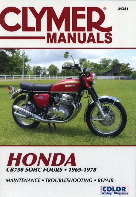
The Honda CB750-4 SOHC Repair Manual 1969-1978 by Clymer covers the following CB750s with Single Over Head Camshaft (SOHC) engines:
- Honda CB750 (K1-K6) 1969-1978
- Honda CB750F 1975-1978
- Honda CB750A Hondamatic (automatic transmission) 1976-1978
The Clymer M341 Honda CB750 SOHC Fours service manual includes color wiring diagrams, a two column layout, step by step instructions, and exploded views to complement the maintenance, service and repair procedures described.
The outstanding content included in a Clymer manual is based on a complete dissassembly and assembly of the Honda CB750 motorcycle. Sure, you can find online sources to give you ideas about what to do and not do for your service project. With a Clymer manual in your toolbox, you have expert repair procedures, tips and strategies at your fingertips so you can be confident in the success of your 1969-1978 Honda CB750 repair/service project.
Book Excerpt: ELECTRICAL SYSTEM
MAGNETIC SWITCH A solenoid switch is used to supply the heavy current for operating the starting motor. When the push button starting switch is pressed, the solenoid coil is energized and becomes an electromagnet that draws the iron core to it. The circuit is completed when the contacts meet. A return spring pulls the iron core back to break the circuit when the push switch is released.
- Remove the left side cover and disconnect the lead from the starting motor (Figure 35). Remove the cover.
- Depress the starter switch and listen for the click of the iron core contacting the coil.
- Check the condition of the contact points and dress with a point file if they are pitted or burned.
WHEELS AND FINAL DRIVE
FRONT WHEEL REMOVAL/DISASSEMBLY Refer to Figure 1 for details of the front wheel assembly.
- Place a block under the front of the engine so the wheel is raised clear off the ground.
- Remove the speedometer cable (Figure 2) at the hub.
- Remove the axle holding nuts. Remove the wheel from the forks.
NOTE: Do not work the brake lever when the wheel is off the motorcycle, or the caliper piston will be forced out of the cylinder.- Unscrew the axle nut (Figure 3) and remove the axle.
- Remove the gearbox for the speedometer.
- On models equipped with lock plates, straighten the lock plates. On all models, unscrew the nuts from the wheel (Figure 4) and remove the disc.
- Remove the bearing retainer from the hub (Figure 5) and remove the dust seal from the retainer.
- Remove the bearing.
Subject: 1969, 1970, 1971, 1972, 1973, 1974, 1975, 1976, 1977, 1978 Honda CB750 K1-K6, CB750F, CB750A service, maintenance, and repair procedures. ISBN-10: 0892871679 | ISBN-13: 9780892871674 | Clymer M341
- General Information
- Troubleshooting
- Lubrication, Maintenance and Tune-up
- Engine
- Clutch and Transmission
- Fuel and Exhaust Systems
- Ignition System
- Front Suspension and Steering
- Rear Suspension
- Brakes
- Body and Frame
- Wiring Diagrams


