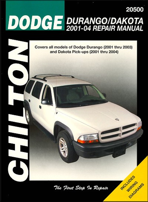
This Haynes repair and service manual, covers 2000-2003 Dodge Durango SUVs and 2000-2004 Dakota pickup trucks. All models, 2WD and 4WD.
Book Excerpt: Dodge Durango 2000-2003, Dakota Pick-Up 2000-2004 Repair Manual FOUR-CYLINDER ENGINE
SUSPENSION AND STEERING SYSTEMS
Subject: 2000, 2001, 2002, 2003, 2004 Dodge Durango SUV, Dakota Pickup service, maintenance, repair. ISBN-10: 1563926776 | ISBN-13: 9781563926778 | Haynes 30022
Book Excerpt: Dodge Durango 2000-2003, Dakota Pick-Up 2000-2004 Repair Manual FOUR-CYLINDER ENGINE
FLYWHEEL/DRIVEPLATE | REMOVAL AND INSTALLATION
(Refer to illustrations 16.3 and 16.4)
- Raise the vehicle and support it securely on jack stands, then refer to Chapter 7 and remove the transmission.
- Remove the pressure plate and clutch disc (see Chapter 8) ( manual transmission equipped vehicles). Now is a good time to check/replace the clutch components and pilot bearing.
- Use paint or a center-punch to make alignment marks on the flywheel/driveplate and crankshaft to ensure correct alignment during reinstallation (see illustration).
- Remove the bolts that secure the flywheel/driveplate to the crankshaft (see illustration). Discard the bolts, as they cannot be reused. If the crankshaft turns, hold the flywheel with a pry bar or wedge a screwdriver into the ring gear teeth to jam the flywheel.
- Remove the flywheel/driveplate from the crankshaft. Since the flywheel is fairly heavy, be sure to support it while removing the last bolt.
- Clean the flywheel to remove grease and oil. Inspect the surface for cracks, rivet grooves, burned areas and score marks. Light scoring can be remove with an emery cloth. Check for cracked and broken ring teeth or a loose ring gear. Lay the flywheel on a flat surface and use a straight edge to check for warpage.
- Clean and inspect the mating surfaces of the flywheel/driveplate and the crankshaft. If the rear seal of the crankshaft is leaking, replace it before reinstalling the flywheel/driveplate.
- Position the flywheel/driveplate against the crankshaft. Be sure to align the marks made during removal. Note that some engines have an alignment dowel or staggered bolt holes to ensure correct installation. Before installing the new bolts, apply thread locking compound to the threads.
CAUTION: The flywheel mounting bolts should only be used once. Replace the bolts if any were used before.- Wedge a screwdriver into the ring gear teeth to keep the flywheel/driveplate from turning as you tighten the bolts to torque listed in this Chapter's Specifications.
- The remainder of installation is the reverse of the removal.
SUSPENSION AND STEERING SYSTEMS
LOWER CONTROL ARM | REMOVAL AND INSTALLATION
(Refer to illustrations 7.8 and 7.9) REMOVAL
- If you are working on a 4WD model, loosen the drive axle/hub nut (see Chapter 8). Also remove the stabilizer bar ( see Section 3).
- Loosen the wheel lug nuts, raise the vehicle and support it securely on jack stands placed under the frame rails. Remove the wheel.
- If you are working on a 4WD model, remove the drive axle (see Chapter 8).
- Remove the shock absorber (see Section 2). Note: On 4WD models it is only necessary to remove the lower mounting bolt.
- Detach the stabilizer bar link from the lower control arm (2WD models) (see Section 3).
- If you're working on a 2WD model, compress the coil spring as described in Section 5.
- If you are working on a 4WD model, remove the torsion bar.
- To disconnect the lower control arm from the steering knuckle, remove the cotter pin from the ball joint castle nut, loosen the nut a few turns (don't remove it), install a ball joint remover and break the ball joint loose from the knuckle. Now remove the nut. NOTE: If you don't have the proper ball joint removal tool, a "picklefork" type ball joint separator can be used , but keep in mind this type of tool will probably damage the ball joint boot (see illustration).
- If present, pry out the plugs in the frame for access to the lower control arm front pivot bolts (see illustration). Remove the lower control arm pivot bolts and pull the lower arm from it's frame brackets.
INSTALLATION- Installation is the reverse of removal. Don't tighten the pivot bolt nuts until the vehicle is back on the ground, at normal ride height, then tighten all fasteners to the torque listed in this Chapter's Specifications. NOTE: You can also raise the lower control arm with a floor jack to simulate normal ride height, then tighten the nuts and bolts.
- Install the wheel and lug nuts. Lower the vehicle and tighten the lug nuts to the torque listed in the Chapter 1 Specifications.
- If you're working on a 4WD model, be sure to check and adjust the ride height (see Section 4).
- Have the front end alignment checked, and if necessary adjusted.
BALL JOINTS | CHECK AND REPLACEMENT
- Inspect the control arm ball joints for looseness anytime either of them is separated from the steering knuckle. See if you can turn the ballstud in it's socket with your fingers. If the ball joint is loose, or if the ballstud can be turned, replace the ball joint. You can also check the ball joints with the suspension assembled as follows.
Subject: 2000, 2001, 2002, 2003, 2004 Dodge Durango SUV, Dakota Pickup service, maintenance, repair. ISBN-10: 1563926776 | ISBN-13: 9781563926778 | Haynes 30022
TABLE of CONTENTS:
- Introduction: Vehicle identification numbers; Buying parts; Maintenance techniques, and more.
- Tune-up and routine maintenance
- Engine and overhaul procedures
- Four-cylinder engine
- 3.9L V6 engine
- 4.7L OHC V8 engine
- Cooling, heating and air-conditioning systems
- Fuel and exhaust systems
- Engine electrical systems
- Emissions control systems
- Manual transmission
- Automatic transmission
- Transfer case
- Clutch and driveline
- Brakes
- Suspension and steering systems
- Body
- Chassis electrical system
- Wiring diagrams


