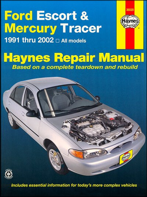
This Haynes DIY repair and service manual, covers Ford Escort and Mercury Tracer cars, 1991 to 2002 with a transversely-mounted four-cylinder engine, coupled to either a 5-speed manual or 4-speed automatic transaxle.
Book Excerpt: 1991-2002 Ford Escort, Mercury Tracer Repair Manual GENERAL ENGINE OVERHAUL PROCEDURES
SUSPENSION AND STEERING SYSTEMS
Subject: 1991, 1992, 1993, 1994, 1995, 1996, 1997, 1998, 1999, 2000, 2001, 2002 Ford Escort, Mercury Tracer service, maintenance, repair. ISBN-10: 156392840X | ISBN-13: 9781563928406 | Haynes 36020
Book Excerpt: 1991-2002 Ford Escort, Mercury Tracer Repair Manual GENERAL ENGINE OVERHAUL PROCEDURES
PISTONS/CONNECTING RODS |- REMOVAL
(Refer to illustrations 12.2, 12.4, 12.5 and 12.7) NOTE: Prior to removing the piston/connecting rod assemblies, remove the cylinder head, the oil pan and the oil pump by referring to the appropriate Sections in Chapter 2A.
- If you're working on a 2.0L Zetec engine, unbolt the lower cylinder block from the bottom of the cylinder block. Tap carefully around the periphery of the lower cylinder block to break the seal, and then remove it from the cylinder block.
- Use your fingernail to feel if a ridge has formed at the upper limit of ring travel (about 1/4-inch down from the top of each cylinder). If carbon deposits or cylinder wear have produced ridges, they must be completely removed with a special tool (see illustration). Follow the manufacturer's instructions provided with the tool. Failure to remove the ridges before attempting to remove the piston/connecting rod assemblies may result in piston breakage.
- After the cylinder ridges have been removed, turn the engine upside-down so the crankshaft is facing up.
- Before the connecting rods are removed, check the endplay with feeler gauges. Slide them between the first connecting rod and the crankshaft throw until the play is removed (see illustration). The end-play is equal to the thickness of the feeler gauges(s). If the endplay exceeds the service limit, new connecting rods will be required. If new rods (or a new crankshaft) are installed, the endplay may fall under the specified minimum (if it does, the rods will have to be machined to restore it - consult an automotive machine shop for advice if necessary). Repeat the procedure for the remaining connecting rods.
- Check the connecting rods and caps for identification marks. If they aren't plainly marked, use a small center-punch to make the appropriate number of indentations on each rod and cap (1,2,3 etc., depending on the engine type and cylinder they're associated with)(see illustration).
- Loosen each of the connecting rod cap nuts 1/2-turn at a time until they can be removed by hand. Remove the number one connecting rod cap and bearing insert. Don't drop the bearing insert out of the cap.
- Slip a short length of plastic or rubber hose over each connecting rod cap bolt to protect the crankshaft journal and cylinder wall as the piston is removed (see illustration).
- Remove the bearing insert and push the connecting rod/piston assembly out through the top of the engine. Use a wooden hammer handle to push on the upper bearing surface in the connecting rod. If resistance is felt, double-check to make sure that all of the ridge was removed from the cylinder.
- Repeat the procedure for the remaining cylinders.
SUSPENSION AND STEERING SYSTEMS
STEERING KNUCKLE AND HUB | REMOVAL, WHEEL BEARING AND SEAL REPLACEMENT AND INSTALLATION REMOVAL
- Remove the hubcap and loosen the driveaxle retaining nut (see Chapter 8).
- Securely block the rear wheels so the vehicle can't roll. Loosen the wheel lug nuts on the side to be disassembled, raise the front of the vehicle and support it securely on jackstands. Remove the wheel and the driveaxle nut. Tap the end of the driveaxle with a hammer and a brass drift to loosen the splines in the hub.
- Remove the brake caliper and support it with a piece of wire as described in Chapter 9. Separate the brake disc from the hub.
Subject: 1991, 1992, 1993, 1994, 1995, 1996, 1997, 1998, 1999, 2000, 2001, 2002 Ford Escort, Mercury Tracer service, maintenance, repair. ISBN-10: 156392840X | ISBN-13: 9781563928406 | Haynes 36020
TABLE of CONTENTS:
Introduction: Vehicle identification numbers. Buying parts. Safety. Maintenance techniques. Chemical and lubricants, and more.
- Tune-up and routine maintenance
- 1.8L engine
- 1.9L engine
- 2.0L SPI engine
- 2.0L Zetec engine
- General engine overhaul procedures
- Cooling, heating and air-conditioning systems
- Fuel and exhaust systems
- Engine electrical systems
- Emissions control systems
- Manual transaxle
- Automatic transaxle
- Clutch and driveaxles
- Brakes
- Suspension and steering systems
- Body
- Chassis electrical system
- Wiring diagrams


