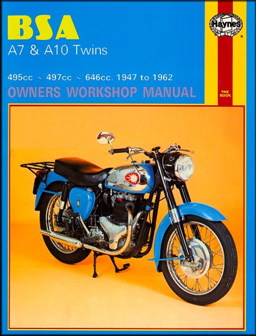
The 1947-1962 Triumph Pre-Unit Twin motorcycles DIY repair manual by Haynes, covers the following models:
Book Excerpt: 1947-1962 Triumph Pre-Unit Twins Repair Manual CLUTCH
IGNITION SYSTEM
Subject: 1947, 1948, 1949, 1950, 1951, 1952, 1953, 1954, 1955, 1956, 1957, 1958, 1959, 1960, 1961, 1962 Triumph Pre-Unit Twins service, maintenance, repair. ISBN-10: 0856962511 | ISBN-13: 9780856962516 | Haynes 251
- Triumph 5T Speed Twin, 1947-1958
- Triumph 6T Thunderbird, 1947-1961
- Triumph T110 Tiger, 1954-1961
- Triumph T120 Bonneville, 1958-1962
- Triumph TR5 Trophy 500, 1951-1958
- Triumph TR6 Trophy 650, 1956-1960
Book Excerpt: 1947-1962 Triumph Pre-Unit Twins Repair Manual CLUTCH
EXAMINING THE CLUTCH PLATES AND SPRINGS
- When the clutch is dismantled for replacement of the clutch plates or during the course of complete overhaul, this is an opportune time to examine all clutch components for signs of wear or damage.
- As mentioned previously, the inserted clutch plates will have to be renewed when the reduction is thickness of the linings reaches 0.030 in. It is important to check the condition of the tongues at the edge of each plate when engage with the grooves in the clutch chainwheel. Even is the clutch linings have not approached the wear limit, it is advisable to renew the inserted plates if the width of the tongues is reduced as a result of wear.
- Both plain and inserted plates should be perfectly flat. Check by laying them on a sheet of plate glass. Discoloration will occur if the plates has overheated; the surface finish of the plates is not too important provided it is smooth and the plates are not buckled.
- The clutch springs will compress during service and take a permanent set. If any spring has reduced in length by more than 0.1 in., all four springs should be renewed- never renew one spring on its own. See Specifications for the original free length measurement.
IGNITION SYSTEM
REMOVING AND REPLACING MAGNETO
- It is not necessary to remove the magneto from the engine unless the engine has to be dismantled completely or the magneto is defective and has to be replaced.
- Before the magneto can be unbolted from the crankcase, the timing cover must be removed and the magneto drive pinion detached from magneto drive shaft. If the pinion is fitted with the integral auto-advance unit, it can be detached easily because the retaining nuts act as an extractor. The nut has a normal right-hand thread; it will slacken initially, then commence to tighten as it draws the pinion off the shaft. Continue unscrewing until the pinion pulls clear. It may be necessary to use a sprocket puller on models fitted with manual advance/retard, because the plain driving pinion is bolted direct to the taper of the magneto drive shaft and has no self-extracting action.
- Before the three nuts retaining the magneto flange to the crankcase are removed, the sparking plugs leads should be detached from the sparking plugs (mark each to ensure correct replacement) and cut-out lead and the advance/retard cable (if fitted). In the latter case it will be necessary to remove the magneto cam ring before the cable can be disengaged.
- Withdraw the three nuts and their spring washers. The magneto will pull off the flange mounting studs, most probably complete with the sealing gasket that could be discarded.
- The magneto is replaced by reversing the dismantling procedure. Note that a new sealing gasket must be used to preserve an oil-tight joint at the rear of the timing cover. When the drive pinion is replaced, the ignition must be re-timed by following the procedure detailed in Chapter 1, section30 and paragraph 31.
Subject: 1947, 1948, 1949, 1950, 1951, 1952, 1953, 1954, 1955, 1956, 1957, 1958, 1959, 1960, 1961, 1962 Triumph Pre-Unit Twins service, maintenance, repair. ISBN-10: 0856962511 | ISBN-13: 9780856962516 | Haynes 251
TABLE of CONTENTS:
- Maintenance
- Engine
- Clutch
- Transmission
- Fuel System and Lubrication
- Ignition System
- Frame and Forks
- Wheels, Brakes and Tires
- Electrical System
- Wiring Diagrams


