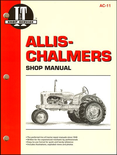
This repair manual covers Allis-Chalmers 5020 and 5030 models.
Book Excerpt: Allis-Chalmers Repair Manual Models 5020, 5030 ROD AND PISTON UNITS ? ALL MODELS
PISTON, RINGS AND CYLINDER ? ALL MODELS
FINAL DRIVE
Subject: Allis-Chalmers 5020, 5030 farm tractor service, maintenance, repair. ISBN-10: 0872880516 | ISBN-13: 9780872880511
Book Excerpt: Allis-Chalmers Repair Manual Models 5020, 5030 ROD AND PISTON UNITS ? ALL MODELS
23. Connecting rod and piston units are removed from above after removing the engine as outlined in paragraph 10, the cylinder head as in paragraph 11, and oil pan as in paragraph 34. Unbolt and remove oil pump. Remove connecting rod cap and push piston and rod assembly up out of cylinder block. Be sure that cylinder ridge is removed before pushing piston out. Connecting rod cap parting line is slanted to offset cap bolts toward crankcase side opening. Parting line is serrated for precise alignment and to remove shear stress from bolt shanks. Tighten connecting rod cap screws to a torque of 49-54 N*m for all models. Special connecting rod bolts do not use spring washers but contact special machined seat in connecting rod cap. Side clearance on journal should be 0.1-0.3 mm.
PISTON, RINGS AND CYLINDER ? ALL MODELS
24. The cam ground aluminum alloy pistons are fitted with two compression rings and one oil ring on 5030 models, while 5020 models have three compression rings and one oil ring. Pistons and rings are available in standard size and 0.5 mm oversize. Examine cylinder bore carefully and rebore to next available oversize if taper exceeds 0.1 mm. Cylinder head surface of block must be flat within 0.1 mm. If cylinder block is machined, be sure that pistons do not project more than 0.5 mm at TDC. Refer to the following specification table.
FINAL DRIVE
AXLE, HOUSING AND FINAL REDUCTION GEARS ? ALL MODELS 151. Remove and Reinstall. To remove final drive assembly, first remove brake cover, drum brake shoes and backing plate as described in paragraph 202. Remove seat pan and lower lift linkage. Remove all of the housing retaining screws, then carefully separate final drive housing (7 ? Fig. 138 or Fig. 141) from center housing. Notice that even though all of the screws are removed, differential pinon housing (27) cannot be removed before housing (7) and final drive gear (9). Final drive should pull straight away from center housing; however, sealer is used on gasket and separation may be difficult. Other final drive can be removed similarly. Be careful not to let differential assembly fall as second drive assembly is removed. Differential assembly can be withdrawn through side opposite differential lock fork. Further disassembly of four wheel drive models will necessitate separation of center housing from transmission housing as outlined in paragraph 130.
Subject: Allis-Chalmers 5020, 5030 farm tractor service, maintenance, repair. ISBN-10: 0872880516 | ISBN-13: 9780872880511
TABLE of CONTENTS:
- Detailed illustrations and exploded views
- Troubleshooting sections covering most models
- Brakes
- Cab
- Cooling system
- Differential
- Electrical system
- Engine
- Final drive
- Axles
- Hydraulics
- Transmission
- Condensed service data information
- Detailed index
- Wiring diagrams for both models
- Accurate information in a concise, easy-to-use format
- Durable, coated paper stands up to messy shop jobs


