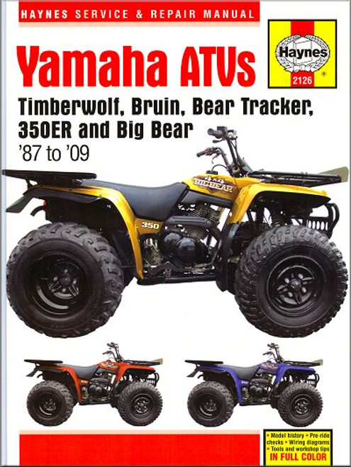
The Yamaha Timberwolf, Bruin, Bear Tracker, 350ER, Big Bear Repair Manual 1987-2009, covers the following ATVs:
- Yamaha YFB250 Timberwolf, 1992-2000
- Yamaha YFM250 Bear Tracker, 1999-2004
- Yamaha YFM250 Bruin 250, 2005-2006
- Yamaha YFM250 Big Bear 250, 2007-2009
- Yamaha YFM350ER, 1987-1995
- Yamaha YFM350FW Big Bear, 1987-1997
- Yamaha YFM350U Big Bear 2X4, 1996-1999
- Yamaha YFM350FWB Big Bear 4X4, 1997-1999
- Yamaha YFM400/YFM40 Big Bear 400 (2WD and 4WD), 2000-2009
Book Excerpt: 1987-2009 Yamaha Timberwolf, Bruin, Bear Tracker, 350ER, Big Bear Repair Manual GENERAL INFORMATION
The front suspension consists of a single lower control arm on each side of the vehicle, connected to the frame by a strut type shock absorber with a concentric coil spring. The rear suspension on all except 2007 and later 400 models consists of a single shock absorber/coil spring assembly and a steel springarm. Rear final drive is by a shaft, which passes through an integral tube on the swingarm and connects with a final drive unit, also mounted on the swingarm. The rear suspension on 2007 and later 400 models is an independent design, using an upper and lower control arm, knuckle and a shock absorber with concentric coil spring on each side of the vehicle. The upper and lower control arms are connected by a stabilizer bar. Final drive is by a shaft, which is connected by a coupling to a universal joint at the front of the final drive unit. The final drive unit is bolted to a subframe and connected to the rear wheel hubs by a pair of driveaxles. On 4WD models, the front wheels are driven by a shaft, which connects the transfer case to the front differential. Power is transmitted from the front differential to a pair of driveaxles, which in turn connect to hubs at the front wheels. The steering system consists of knuckles mounted at the outer ends of the front suspension and connected to a steering shaft by tie-rods. The steering shaft is turned by a one-piece handlebar.HANDLEBAR | REMOVAL, INSPECTION AND INSTALLATION
The handlebar is a one-piece tube. The tube fits into a bracket, which is integral with the steering shaft. If the handlebar must be removed for access to other components, such as the steering shaft, simply unplug the electrical connectors, remove the bolts and lift the handlebar off the bracket. It isn't necessary to detach cables or wires from the handlebar, but it is a good idea to support the assembly with a piece of wire or rope, to avoid unnecessary strain on the cables.
The Haynes 2126 manual is a "Superbike" book". The Superbike is a special Haynes Motorcycle manual that includes many extra features such as: color sections for wiring diagrams, performance data, model history and tools / workshop tips.
The cover of this manual is UV coated to help protect it against the shop environment.
The Motor Bookstore employs Fast and Free Shipping and offers the best prices on the market. Our 30 day money back guarantee policy allows you to shop worry free. Pick up the Haynes 2126 manual today so you can start saving on all of your service and repair costs tomorrow.
Subject: 1987, 1988, 1989, 1990, 1991, 1992, 1993, 1994, 1995, 1996, 1997, 1998, 1999, 2000, 2001, 2002, 2003, 2004, 2005, 2006, 2007, 2008, 2009 Yamaha Timberwolf, Bruin, Bear Tracker, 350ER, Big Bear service, maintenance, and repair procedures. ISBN-10: 1620921138 | ISBN-13: 9781620921135 | Haynes 2126
- Identification numbers
- Buying parts
- Engine/transmission oil level check
- Brake fluid level check
- Tire checks
- Specifications
- Recommended lubricants and fluids
- Maintenance schedule
- Component locations
- Maintenance procedures
- Engine, clutch and transmission (all models)
- Fuel and exhaust systems
- Ignition system
- Steering, suspension and final drive
- Brakes
- Wheels
- Tires
- Bodywork and frame (all models)
- Dimensions and weights
- Tools and workshop tips
- Security
- Lubricants and fluids
- Conversion factors
- Storage
- Troubleshooting
- Technical terms explained
- Trail rules


