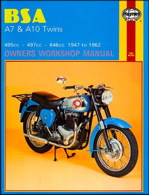
This BSA A7 & A10 Twins repair manual by Haynes covers 1947-1950 BSA A7 495cc Twins; 1950-1962 BSA A7 497cc Twins; and 1950-1962 BSA A10 646cc Twins. All models, with rigid, plunger and swingarm frames.
Book Excerpt: 1947-1962 BSA A7, A10 Twins Repair Manual CHAPTER 1 | ENGINE
REMOVING THE ENGINE FROM THE FRAME
- Before further dismantling takes place, it is convenient at this stage, to remove the engine from the frame. Drain the oil tank and disconnect both oil pipes at the point where they join the bottom of the timing chest, close to the oil pump. Remove also the sump plate and gauze from the base of the crankcase, which is retained by four small nuts and washers. This will permit all excess oil to drain from the crankcase.
- Remove the cut-out lead from the end cover of the magneto. Remove the clutch operating cable in the case of the early unit-construction models, the speedometer drive cable and the advance/retard cable (where fitted).
- Remove the chain guard over the final drive chain and the chain itself, by withdrawing the spring link (unit-construction models only).
- The engine of the swinging arm models is retained in the frame by four bolts, two of which pass through the front engine plates and two through the rear. When these bolts are withdrawn, the engine can be lifted forward and upward until it is clear of the frame. Later models will have metal cases that surround the dynamo still in position. Special care is necessary to prevent the dynamo clamp from fouling the right hand frame tube during the lifting out operation.
CHAPTER 7 | WHEELS, BRAKES AND TIRES
FRONT BRAKE ASSEMBLY: EXAMINATION, RENOVATION AND REASSEMBLY
- The front wheel can be removed and the brake assembly complete with brake plate dethatched by following the procedures given in Chapter 6, Section 2, paragraphs 2 and 3.
- Before dismantling the brake assembly, examine the condition of the brake linings. If they are wearing thin or unequally, they must be replaced.
- To remove the brake shoes from the brake plate, position the operating cam so that the shoes are in the fully-expanded position and pull them apart while lifting them upwards, in the form of a "V". When they are clear of the brake plate the return springs should be removed and the shoes replaced.
- It is possible to replace the brake linings fitted with rivets and not bonded on, as is the current practice. Much will depend on the availability of the original type of linings; service-exchange brake shoes with bonded-on linings may be the only practical form of replacement.
- If new linings are fitted by riveting, it is important that the rivet heads are countersunk, otherwise they will rub on the brake drum and be dangerous. Make sure the lining is in very close contact with the brake shoe during the riveting operation; a small "C" clamp of the type used by carpenters can often be used to good effect until all rivets are in position. Finish off by chamfering off the end of each shoe, otherwise fierce brake grab may occur due to the pick-up of the leading edge of each lining.
- Before replacing the brake shoes, check that the brake operating cam can be removed for greasing by unscrewing the nut on the end of the brake operating arm and drawing the arm off so that the cam spindle can be withdrawn from the inside of the brake plate.
Subject: 1947, 1948, 1949, 1950, 1951, 1952, 1953, 1954, 1955, 1956, 1957, 1958, 1959, 1960, 1961, 1962 BSA A7, A10 Twin service, maintenance, and repair instructions. ISBN-10: 08569612130 | ISBN-13: 9780856961212 | Haynes 121
TABLE of CONTENTS:
- Maintenance
- Engine, clutch and transmission
- Fuel system and lubrication
- Ignition system
- Frame and forks
- Wheels, brakes and tires
- Electrical system
- Wiring diagrams


Above: Marco Centeno restored his 1958 BSA A10 Super Rocket to beautiful original condition. Mexico.