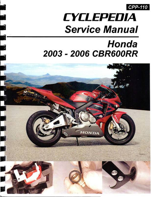
This DIY repair and service manual by Haynes, covers 2003-2006 Honda CBR600RR sportbikes.
Book Excerpt: 2003-2006 Honda CBR600RR Repair Manual ENGINE, CLUTCH AND TRANSMISSION
STARTER CLUTCH AND GEARS | INSPECTION
- With the starter clutch face down on a workbench, check that the starter driven gear rotates freely clockwise and locks against the rotor anti-clockwise (see illustration). If it doesn't, the starter clutch should be dismantled for further investigation.
- Withdraw the starter driven gear from the starter clutch (see illustration). If the gear appears stuck, rotate it clockwise as you withdraw it to free it from the starter clutch. Remove the needle bearing.
- Check the condition of the sprags inside the clutch body - if they are damaged, marked or flattened at any point, the sprag assembly must be replaced with a new one (see illustration). To remove the sprag assembly release the circlip that holds it and note which way round it fits. Install the new assembly in a reverse sequence. Secure the sprag assembly with the circlip. Apply clean engine oil to the sprags.
- Check the external surface on the driven gear hub (see illustration 13.7). Measure the outside diameter of the hub and check that it has not worn beyond the service limit specified. Check the needle roller bearing and the bearing surfaces on the starter driven gear hub and the starter clutch housing boss. If the bearing surfaces show signs of excessive wear or the bearing itself is worn or damaged, they should be replaced with new ones.
ELECTRICAL SYSTEM
ALTERNATOR | CHECK
- Remove the fairing left-hand side panel (see Chapter 7).
- Trace the wiring from the alternator and disconnect it at the white 3-pin wiring connector with the three yellow wires (see illustration). Check the connector terminals for corrosion and security.
- Using a multimeter set to the ohms x 1 (ohmmeter) scale measure the resistance between each of the yellow wires on the alternator side of the connector, taking a total of three readings, then check for continuity between each terminal and ground (earth).
If the stator coil windings are in good condition the three readings should be within range shown in the Specifications at the start of this Chapter, and there should be no continuity between any of the terminals and ground. If not, the alternator stator coil assembly is at fault and should be replaced with a new one. Note: Before condemning the stator coils, check the fault is not due to damaged wiring between the connector and the coils. REMOVAL- Remove the fairing left-hand side panel (see Chapter 7).
- Either drain the engine oil (see Chapter 1), or place a container under the engine to catch the oil that will come out when the alternator cover is removed. If you have an auxiliary stand, place the bike on it so that it is level - this minimizes oil loss. If you do not have an auxiliary stand it is best to drain the oil.
Subject: 2003, 2004, 2005, 2006 Honda CBR600RR service, maintenance, and repair instruction. ISBN-10: 1785210025 | ISBN-13: 9781785210020 | Haynes 4590
TABLE of CONTENTS:
LIVING WITH YOUR HONDA CBR600RR
- Identification numbers
- Buying spare parts
- Engine oil level
- Brake fluid levels
- Tires
- Bike specs
- Routine maintenance and servicing
- Specifications
- Lubricants and fluids
- Maintenance schedule
- Component locations
- Maintenance procedures
- Engine, clutch and transmission
- Cooling systems
- Engine management system
- Frame and suspension
- Brakes (ABS), wheels and final drive
- Bodywork
- Electrical system
- Color wiring diagrams
- Tools and workshop tips
- Security
- Storage
- Troubleshooting


