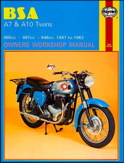
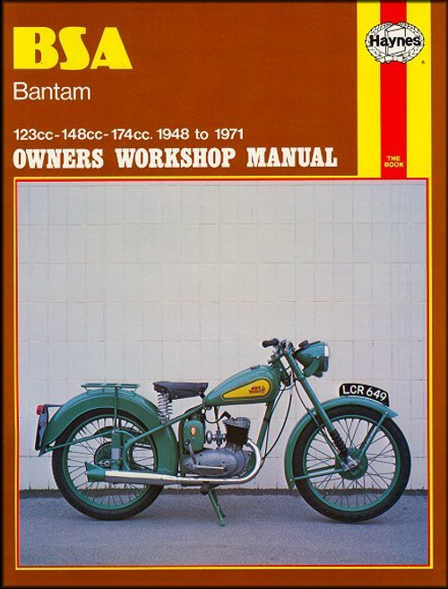
This Haynes repair manual covers 1962-1973 BSA motorcycles, including the following models:
Book Excerpt: 1962-1973 BSA A50, A65 Twins Repair Manual ENGINE, CLUTCH AND TRANSMISSION
WHEELS, BRAKES AND TIRES
Subject: 1962, 1963, 1964, 1965, 1966, 1967, 1968, 1969, 1970, 1971, 1972, 1973 BSA A50, A65 Twins service, maintenance, repair. ISBN-10: 0856961558 | ISBN-13: 9780856961557 | Haynes 155
- BSA A50 Star Twin, 499cc
- BSA A50C Cyclone, 499cc
- BSA A50IR Royal Star, 499cc
- BSA A50W Wasp, 499cc
- BSA A65 Star Twin, 654cc
- BSA A65IT Thunderbolt, 654cc
- BSA A65-2H Hornet, 654cc
- BSA A65FB Firebird, 654cc
- BSA A65L Lightning, 654cc
- BSA A65R Rocket, 654cc
- BSA A65-2S Spitfire, 654cc
Book Excerpt: 1962-1973 BSA A50, A65 Twins Repair Manual ENGINE, CLUTCH AND TRANSMISSION
ENGINE REASSEMBLY | REPLACING PUSHRODS AND CYLINDER HEAD
- Place a new cylinder head gasket in position and slacken off the inlet rockers completely. Place the head in position over the four studs, screw in the five cylinder head bolts and replace the four nuts and washers on the studs. Tighten down each a little at a time criss-crossing the head from the center outwards to minimize distortion. Do not forget the short bolt inside the push rod tower; this bolt cannot be fitted with the push rods in situ. Using a torque wrench tighten the bolts to 25 ft. lb and the nuts to 25 ft. lb.
- When the cylinder head is finally torqued down replace the two short push-rods on the two outer tappets and under the inlet (rear) rocker arms. Assemble the exhaust (front) rockers in the order detailed in Fig 1.1 with the adjuster screws over the valves and fit the two long pushrods on the two inner tappets and under the exhaust rocker ball pins. With the exhaust rocker assembly in place replace and tighten the rocker spindle nut.
ENGINE REASSEMBLY | TAPPET ADJUSTMENT
- To set the tappets (or valve clearance) the valve must be in the correct position, that is with the cam follower (tappet) on the base circle of the cam as follows:
- Left-hand inlet valve spring fully compressed. Set the right-hand inlet valve.
- Right-hand inlet valve spring fully compressed. Set the left hand inlet valve.
- Left-hand exhaust valve spring fully compressed. Set the right-hand exhaust valve.
- Right-hand exhaust valve spring fully compressed. Set the left-hand exhaust valve.
- With the valve in the correct position check the gap with the appropriate feeler gauge. 0.008 in inlet clearance and 0.010 in. exhaust clearance. If adjustment is required, slacken off the locknut and screw the square adjuster in or out as necessary. Always recheck the setting after tightening the locknut.
- Clean the mating surfaces of the rocker box and cover and apply some jointing compound. Position a new gasket and replace the rocker box cover tightening it down with its six domed nuts and washers.
WHEELS, BRAKES AND TIRES
REAR WHEEL | REMOVAL AND EXAMINATION
- Place the machine on the centerstand and before removing the wheel, check for rim alignment, loose or broken spokes and other defects by following the procedure applying to the front wheel in Section 2.
- Two types of rear wheel have been fitted, the standard or the quickly detachable type. The latter has the advantage of simplified removal, leaving the final drive chain and sprocket in position. The option is no longer available with the latest conical hub wheel which is not made in the quickly detachable version.
- If the wheel is of the standard type, commence by disconnecting the final drive chain at the detachable spring link. The task is made easier if the link is first positioned so that it is on the rear wheel sprocket. Unwind the chain off the rear sprocket and lay it on a clean surface.
- Take off the brake rod adjuster and pull the brake rod clear of the brake operating arm. Disconnect the torque stay by removing the nut where the stay joins the rear brake plate. If the stop lamp stays in the 'on' position disconnect the snap connector in the lead.
Subject: 1962, 1963, 1964, 1965, 1966, 1967, 1968, 1969, 1970, 1971, 1972, 1973 BSA A50, A65 Twins service, maintenance, repair. ISBN-10: 0856961558 | ISBN-13: 9780856961557 | Haynes 155
TABLE of CONTENTS:
- Maintenance
- Engine, clutch and transmission
- Fuel system and lubrication
- Ignition system
- Frame and forks
- Wheels, brakes and tires
- Electrical system
- Wiring diagrams


