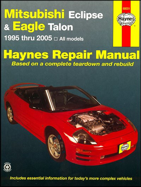
This DIY repair and service manual by Chilton, covers 1999-2005 Mitsubishi Eclipse, U.S. and Canadian models. Complete maintenance, service and repair information for the do-it-yourself mechanic.
Book Excerpt: 1999-2005 Mitsubishi Eclipse Repair Manual FUEL AND EXHAUST SYSTEMS
BODY
Subject: 1999, 2000, 2001, 2002, 2003, 2004, 2005 Mitsubishi Eclipse service, maintenance, repair. ISBN-10: 1563927381 | ISBN-13: 9781563927386 | Chilton 50401
Book Excerpt: 1999-2005 Mitsubishi Eclipse Repair Manual FUEL AND EXHAUST SYSTEMS
FUEL INJECTION SYSTEM | GENERAL INFORMATION The sequential Multi-Port Fuel Injection (MPFI) system consists of three sub-systems: air intake, engine control and fuel delivery. The MPFI system is controlled by the Powertrain Control Module (PCM) which uses the information from various sensors to determine the proper air/fuel ratio under all operating conditions. The fuel injection, emissions and engine control systems work together to provide maximum performance, fuel economy and the lowest exhaust emissions. For complete information on the emissions and engine control systems, refer to Chapter 6.
AIR INTAKE SYSTEM The air intake system consists of the air filter, the air ducts, air inlet resonator, the throttle body, the idle control system and the intake manifold. The engine idle speed is controlled by the PCM via the Idle Air Control (IAC) motor. The IAC motor regulates the flow of air allowed to bypass the throttle valve in the throttle body, thereby increasing engine speed. The PCM uses information from various sensors to determine the correct amount of airflow required to maintain the proper engine speed during engine warm-up and when a load is placed on the engine, such as engaging the air conditioning compressor, low speed steering or when an automatic transaxle is placed in gear.
ENGINE CONTROL SYSTEM
(For information on the engine control system, refer to Chapter 6).
FUEL DELIVERY SYSTEM The fuel delivery system consists of the following components: an electric fuel pump, a fuel pressure regulator, an in-line fuel filter, the fuel rail, the fuel injectors, various metal and plastic lines, the Automatic Shutdown (ASD) relay and the fuel pump relay. The fuel pump is located inside the fuel tank. Fuel is drawn through the fuel inlet strainer into the pump, then through the fuel filter and delivered to the injectors. The fuel pressure regulator maintains a constant fuel pressure to the injectors. Excess fuel is released back into the tank through the fuel pressure regulator, which is mounted on the fuel rail on all except 2.0L non-turbo models. On these models it is mounted in the line leading from the fuel tank. The fuel rail supplies the regulated fuel to each electronically supplied fuel injector. The injectors are solenoid types consisting of a solenoid, plunger, needle valve and housing. When the PCM sends a voltage signal to the fuel injector, the needle valve raises off its seat and lets metered fuel enter the intake manifold. The injection quantity is determined by the length of time which the current is supplied to the injector. The MFI relay (also known as the auto-shutdown or ASD relay) and the fuel pump relay are located next to each other, in the passenger compartment or engine compartment depending on the model. The MFI relay connects battery voltage to the fuel injectors and the ignition coil while the fuel pump relay connects battery voltage only to the fuel pump. If the PCM senses there is NO signal from the camshaft of crankshaft sensors while the ignition key is RUN or cranking, the PCM will de-energize both relays in approximately one second.
BODY
DOOR TRIM PANEL | REMOVAL AND INSTALLATION
(Refer to illustrations 13.2, 13.3 and 13.5)
- Disconnect the negative cable from the battery.
- Remove the window crank on manual regulator equipped models by working a cloth back-and-forth behind the handle to dislodge the clip (see illustration).
- Remove any door trim panel retaining screws and door pull/arm rest assemblies (see illustration).
- Insert a wide putty knife or screwdriver between the trim panel and door to disengage the retaining clips. Work around the outer edge until the panel is free.
- Once all of the clips are disengaged, detach the trim panel, disconnect any electrical connectors and remove the trim panel from the vehicle by gently pulling it up and out (see illustration).
- For access to the inner door, peel back the plastic waterproof film, taking care not to tear it. To install the trim panel, first press the waterproof film into place.
- Prior to installation of the door panel, be sure to reinstall any clips in the panel which may have come out during the removal procedure and stayed in the door.
- Plug in any electrical connectors and place the panel in position. Press it into place until the clips are seated and install any retaining screws and armrest/door pulls. Install the manual regulator window crank.
Subject: 1999, 2000, 2001, 2002, 2003, 2004, 2005 Mitsubishi Eclipse service, maintenance, repair. ISBN-10: 1563927381 | ISBN-13: 9781563927386 | Chilton 50401
TABLE of CONTENTS:
Introduction: About this manual | Introduction | Vehicle identification numbers | Maintenance techniques, tools and working facilities | Buying parts | Jacking and towing | Booster battery (jump) starting | Conversion factors | Automotive chemicals and lubricants | Safety first! | Troubleshooting
- Tune-up and routine maintenance
- Four-cylinder non-turbo engine
- Four-cylinder turbo engine
- V6 engine
- General engine overhaul procedures
- Cooling, heating and air-conditioning systems
- Fuel and exhaust systems
- Engine electrical systems
- Emissions and engine control systems
- Manual transaxle
- Automatic transaxle
- Clutch and driveline
- Brakes
- Suspension and steering systems
- Body
- Chassis electrical system
- Wiring diagrams


