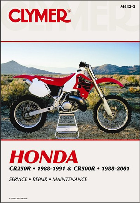
The 1997-2001 Honda CR250R repair manual by Clymer, covers 250cc motocross models.
Book Excerpt: 1997-2001 Honda CR250R Repair Manual EXHAUST VALVE SYSTEM
IGNITION TIMING
Subject: 1997, 1998, 1999, 2000, 2001 Honda CR250R service, maintenance, repair. ISBN-10: 0892877898 | ISBN-13: 9780892877898 | Clymer M437
Book Excerpt: 1997-2001 Honda CR250R Repair Manual EXHAUST VALVE SYSTEM
The exhaust valve system ( Honda Composite Racing Valve) is designed to broaden the power band from low to high engine speeds. This is achieved by varying the exhaust port timing, and the amount of exhaust pulse to the expansion chamber. The exhaust valve system consists of three major assemblies, as shown in Figure 55. These assemblies are:At low engine speeds, the flap valve closes the timed exhaust port, and the exhaust valves route a portion of the exhaust to a sub exhaust chamber, cast into the cylinder. This alters the exhaust pulse to the expansion chamber and enhances low-end power. As engine speed increases, the flap valve opens and the exhaust valves close, routing the complete exhaust pulse to the expansion chamber and realizing the full power potential.
- Sub exhaust valves and flap valve. This also includes the shafts, bearings and flap valve. These parts are located in the cylinder.
- Exhaust valve linkage. This includes the valve link assembly and drive shaft. These parts are located in the cylinder.
- Exhaust valve governor and linkage. This includes the governor assembly, rack and pinion shaft. These parts are located in the crankcase.
IGNITION TIMING
The ignition timing is electronically controlled by the ignition control module. No routine adjustment of the timing is necessary. Check the timing when ignition system problems are suspected, or whenever the ignition control module, stator, ignition pulse generator or flywheel are replaced.
- Warm up the engine to operating temperature.
- Remove the alternator cover ( Figure 29) as described in this chapter.
- Check that the stator index mark is aligned with the index mark on the crankcase cover (Figure 30). If the marks are not aligned, loosen the two bolts securing the stator (Figure 12) and realign the marks.
- Connect a timing light and tachometer following the manufacturer??s instructions.
- Start the engine and hold the speed at 3000 rpm.
- Direct the timing light at the index marks on the flywheel and stator. The stator index mark should align between the F marks on the flywheel ( Figure 30).
Subject: 1997, 1998, 1999, 2000, 2001 Honda CR250R service, maintenance, repair. ISBN-10: 0892877898 | ISBN-13: 9780892877898 | Clymer M437
TABLE of CONTENTS:
- General Information
- Troubleshooting
- Lubrication, Maintenance and Tune-up
- Engine
- Clutch and External Gearshift Linkage
- Transmission and Internal Shift Mechanism
- Fuel and Emission Systems
- Exhaust System
- Electrical System
- Wheels, Tires and Drive Chain
- Front Suspension and Steering
- Rear Suspension
- Brakes
- Body and Frame
- Wiring Diagrams


