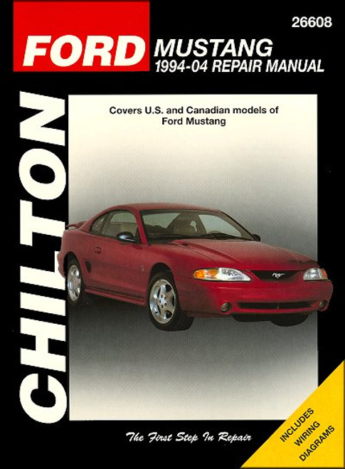
This Chilton repair and service manual covers 1994-2004 Ford Mustang cars, US and Canadian models powered by V6 and V8 engines. Note: this manual DOES NOT include information on independent or rear suspension/driveaxles on 1999 and later Cobra models, or info on the 4.6L Supercharged Cobra models.
Book Excerpt: 1994-2004 Ford Mustang Repair Manual V6 AND 5.0L V8 ENGINES
FUEL AND EXHAUST SYSTEMS
Subject: 1994, 1995, 1996, 1997, 1998, 1999, 2000, 2001, 2002, 2003, 2004 Ford Mustang service, maintenance, repair. ISBN-10: 1563926490 | ISBN-13: 9781563926495 | Chilton 26608
Book Excerpt: 1994-2004 Ford Mustang Repair Manual V6 AND 5.0L V8 ENGINES
CAMSHAFT, BALANCE SHAFT AND BEARINGS | REMOVAL, INSPECTION AND INSTALLATION NOTE: 1998 and later 3.8L V6 models are equipped with a balance shaft that is driven by a gear on the camshaft. 1994 through 1997 models are not equipped with the balance shaft system. Be sure to follow the correct procedure. CAMSHAFT LOBE LIFT CHECK
- In order to determine the extent of cam lobe wear, the lobe lift should be checked prior to camshaft removal. Refer to Section 4 and remove the valve covers. The rocker arms must also be removed (see Section 5), but leave the pushrods in place.
- Position the number one piston at TDC on the compression stroke (see Section 3).
- Beginning with the number one cylinder mount a dial indicator on the engine and position the plunger in-line with and resting on the first rocker arm (see illustration 11.4).
- Zero the dial indicator, and then very slowly turn the crankshaft in the normal direction of rotation until the indicator needle stops and begins to move in the opposite direction. The point at which it stops indicates maximum cam lobe lift.
- Record this figure for future reference, and then reposition the piston at TDC on the compression stroke.
- Move the dial indicator to the remaining number one cylinder pushrod and repeat the check. Be sure to record the results for each valve.
- Repeat the check for the remaining valves. Since each piston must be at TDC on the compression stroke for this procedure, work from cylinder-to-cylinder following the firing order sequence (see Section 3).
- After the check is complete, compare the results to the Specifications. If camshaft lobe lift is less than specified, cam lobe wear has occurred and a new camshaft should be installed.
FUEL AND EXHAUST SYSTEMS
ACCELERATOR CABLE | REMOVAL, INSTALLATION AND ADJUSTMENT REMOVAL
(Refer to illustrations 10.2a, 10.2b, 10.3, 10.5 and 10.6)
- Remove the air intake duct from the throttle body and intake manifold area (see Section 9).
- On all models except 2001 and later 3.8L models, detach the accelerator cable from the throttle lever (see illustration). On 2001 and later 3.8L models, detach the accelerator cable from the throttle wheel.
- Remove the cruise control cable from the bracket (see illustration).
- Separate the accelerator cable from the cable bracket.
- Push the accelerator cable nylon bushing out of the accelerator pedal and shaft arm, pull the cable end out from the accelerator pedal recess in the driver's compartment (see illustration).
- Disconnect any cable clips or brackets securing the accelerator cable (see illustration). On 2001 and later models, remove the bolts securing the cable bracket to the firewall.
- Remove the throttle cable through the firewall from the engine compartment.
Subject: 1994, 1995, 1996, 1997, 1998, 1999, 2000, 2001, 2002, 2003, 2004 Ford Mustang service, maintenance, repair. ISBN-10: 1563926490 | ISBN-13: 9781563926495 | Chilton 26608
TABLE of CONTENTS:
Introduction: About this manual | Introduction | Vehicle identification numbers | Maintenance techniques, tools and working facilities | Buying parts | Jacking and towing | Booster battery (jump) starting | Conversion factors | Automotive chemicals and lubricants | Safety first! | Troubleshooting
- Tune-up and routine maintenance
- Engine and overhaul procedures
- V6 and 5.0L V8 engines
- 4.6L V8 engines
- Cooling, heating and air-conditioning systems
- Fuel and exhaust systems
- Engine electrical systems
- Emissions control systems
- Manual transmission
- Automatic transmission
- Clutch and drivetrain
- Brakes
- Suspension and steering systems
- Body
- Chassis electrical system
- Wiring diagrams


