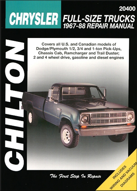
Book Excerpt: 1967-1988 Dodge Ramcharger, Plymouth Trail Duster Repair Manual ENGINE AND ENGINE OVERHAUL
CYLINDER LINERS AND SEALS | INSPECTION
- Check the front plate mounting surface and flywheel housing for distortion.
- Using a straightedge, check the cylinder block mating surface. The mating surface must be flat within 0.003 in. (0.076mm). If distortion exceeds 0.008 in (0.2mm), the block surface may be reground.
NOTE: Do not grind more than necessary to make specifications.- Measure the ID of the sleeve at three points: top (where stepped wear usually occurs), middle and bottom with an inside micrometer or a telescope gauge. Measurements should be both parallel to, and at right angles with, the crankshaft centerline at each point.
- The sleeve ID should be 3.6200-3.6213 in. (92.000-92.035mm). Allowable out-of-round is 0.003 in. (0.076mm) or less, and allowable taper is 0.002 in. (0.05mm) or less. If the ID deviates by more than the standard diameter of 0.047 in. (1.20mm), the sleeve must be replaced. If ID deviation is 0.009 in.-0.047 in. (0.25mm-1.20mm) the sleeve may be bored to an oversize of 0.009 in.-0.039 in. (0.25mm-1.00mm), in increments of 0.009 in (0.25mm).
DRIVE TRAIN | FRONT DRIVE AXLE
MANUAL LOCKING HUBS | REMOVAL AND INSTALLATION WARN HUBS
(See Figure 46)
- Straighten the lock tabs and remove the six hub mounting bolts.
- Tap the hub gently with a mallet to remove.
- Separate the clutch assembly from the body assembly.
- Remove the snap ring form the rear of the body assembly, using snap ring pliers. Slip the axle shaft hub out of the body from the front.
- Remove the Allen screw from the inner side of the clutch, and remove the bronze dial assembly from the front side of the clutch housing assembly.
- Remove the clutch assembly from the rear of the housing, complete with the twelve roller pins.
TO INSTALL:- Coat the moving parts with a waterproof grease.
- Slide the axle shaft hub into the body from the front, and replace the snap ring.
- Replace the bronze dial assembly and inner clutch. Tighten the Allen screw and stake the edge of the screw with a center punch to prevent loosening.
- With the dial in the free position, rotate the outer clutch body into the inner assembly until it bottoms in the housing. Back it up to the nearest hole and install the roller pins.
- Position the hub and clutch assembly together with a new gasket in between.
- Position the hub assembly over the end of the axle and replace the six hub mounting bolts and lock tabs.
Subject: 1967, 1968, 1969, 1970, 1971, 1972, 1973, 1974, 1975, 1976, 1977, 1978, 1979, 1980, 1981, 1982, 1983, 1984, 1985, 1986, 1987, 1988 Dodge, Plymouth service, maintenance, repair. ISBN-10: 0801986621 | ISBN-13: 9780801986628 | Chilton 20400
TABLE of CONTENTS:
Introduction: About this manual | Introduction | Vehicle identification numbers | Maintenance techniques, tools and working facilities | Buying parts | Jacking and towing | Booster battery (jump) starting | Conversion factors | Automotive chemicals and lubricants | Safety first! | Troubleshooting
- Tune-up and routine maintenance
- Engine and overhaul procedures
- Cooling, heating and air-conditioning systems
- Fuel and exhaust systems
- Engine electrical systems
- Emissions control systems
- Transmission
- Brakes
- Suspension and steering systems
- Body
- Chassis electrical system
- Wiring diagrams


