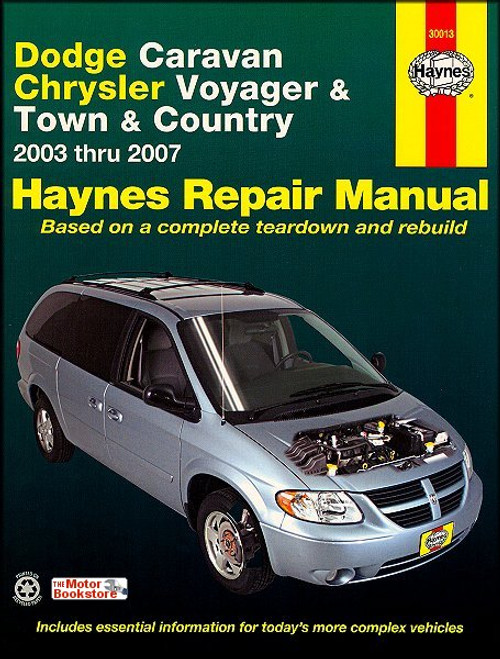
The 2003-2007 Dodge Caravan, Plymouth Voyager, Chrysler Town & Country Repair Manual by Chilton, covers all U.S. and Canadian models.
These minivans are front-engine, front-wheel drive models, available in either standard length and long length bodies. They come equipped with a standard rear liftgate door and sliding side doors on both sides of the vehicle.
They are powered by transversely-mounted 2.4L 4-cylinder or 3.3L and 3.8L V6 engines, equipped with electronic multi-port injection.
Book Excerpt: 2003-2007 Dodge Caravan, Plymouth Voyager, Chrysler Town & Country Repair Manual FUEL AND EXHAUST
FUEL PUMP, FUEL PRESSURE REGULATOR, FUEL LEVEL SENDING UNIT ASSEMBLY | REMOVAL AND INSTALLATION
- Relieve the system fuel pressure (see Section 2).
- Disconnect the cable from the negative battery terminal (see Chapter 5, Section 1).
- Remove the fuel tank (see Section 5).
- Disconnect the fuel delivery line quick-connect fitting from the fuel pump/fuel pressure regulator/fuel level sending unit assembly (see illustration).
- Disconnect the electrical connector from the fuel pump/fuel pressure regulator/fuel level sending unit assembly.
- Before removing the fuel pump/fuel pressure regulator/fuel level sending unit assembly, make an alignment mark on the mounting flange for the fuel pump/fuel pressure regulator/fuel level sending unit and on the fuel tank (see illustration). This mark ensures that the assembly will be correctly realigned when it?s installed again.
- Using a brass punch and hammer, loosen the locknut that secures the fuel pump/fuel pressure regulator/fuel level sending unit assembly (see illustration).
- Carefully lift the fuel pump/fuel pressure regulator/fuel level sending unit assembly from the fuel tank (see illustration). Angle the module so that you don?t bend the float arm of the fuel level sending unit or damage the fuel pump inlet strainer.
- If you want to replace the fuel pressure regulator, see Section 9. If you want to replace the fuel pump or fuel level sending unit, see Section 10.
- While the pump is removed, inspect the pump inlet strainer. Make sure that it?s not clogged or damaged. If the inlet strainer is dirty, try washing it in clean solvent. If it?s still clogged, replace it.
- Installation is the reverse of the removal. Be sure to tighten the fuel pump module locknut securely.
SUSPENSION AND STEERING SYSTEMS
CONTROL ARM | REMOVAL, INSPECTION AND INSTALLATION REMOVAL NOTE: New lower control arm pivot bolts will be required for installation.
- Loosen the wheel lug nuts, raise the front of the vehicle and support it securely on jackstands. Remove the wheel.
- Remove the steering knuckle (see Section 8).
- Remove the subframe/cradle reinforcement plate. (see Section 16).
- If you?re removing the right control arm, remove the control arm pivot bolt and discard it and then remove the control arm (see illustration).
- If you?re removing the left control arm, support the left side of the subframe/cradle with a floor jack and loosen (but do not remove) the left subframe/cradle bolt (see illustration). Mark the relationship between the subframe/cradle and chassis and then carefully lower the subframe/cradle enough to remove the left pivot bolts.
NOTE: The pivot bolt cannot clear the transmission without lowering the subframe/cradle.- Remove the pivot bolt and discard it, then remove the control arm.
INSPECTION- Make sure the control arm is straight. If it is bent, replace it. Do not attempt to straighten a bent control arm.
- Inspect all bushings for cracks, distortion and tears. If a bushing is torn or worn, take the assembly to an automotive machine shop and have it replaced.
NOTE: Rear bushings designed with a slit can be removed and replaced easily without having to take the control arm to a machine shop.
Subject: 2003, 2004, 2005, 2006, 2007 Dodge Caravan, Plymouth Voyager, Chrysler Town & Country service, maintenance, repair. ISBN-10: 1563928574 | ISBN-13: 9781563928574 | Chilton 20303
- Tune-up and routine maintenance
- 2.4L four-cylinder engine
- 3.3L and 3.8L V6 engines
- General engine and overhaul procedures
- Cooling, heating and air-conditioning systems
- Fuel and exhaust systems
- Engine electrical systems
- Emissions and engine control systems
- 4-speed automatic transaxle
- Driveaxles
- Brakes
- Suspension and steering systems
- Body
- Chassis electrical system
- Wiring diagrams


