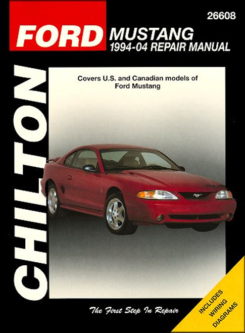
This DIY repair manual by Haynes, covers 1994-2004 Ford Mustang cars, 2-door sport coupes and convertibles. These Mustangs are powered by a 3.8L V6, SOHC-2V 4.6L V8, DOHC-4V 4.6L V8, and 5.0L V8 engines. Note: this manual DOES NOT include information on independent rear suspension/driveaxles on 1999 or later Cobra models nor information on 4.6L Supercharged Cobra models.
Book Excerpt: 1994-2004 Ford Mustang Repair Manual 4.6L V8 ENGINES
CRANKSHAFT PULLEY/VIBRATION DAMPER | REMOVAL AND INSTALLATION
AUTOMATIC TRANSMISSION
SUSPENSION AND STEERING SYSTEMS
Subject: 1994, 1995, 1996, 1997, 1998, 1999, 2000, 2001, 2002, 2003, 2004 Ford Mustang service, maintenance, repair. ISBN-10: 1563926768 | ISBN-13: 9781563926761 | Haynes 36051
Book Excerpt: 1994-2004 Ford Mustang Repair Manual 4.6L V8 ENGINES
GENERAL INFORMATION This part of chapter 2 is devoted to in-vehicle repair procedures for the 4.6L Single Overhead Camshaft (SOHC) and the 4.6L Double Overhead Camshaft (DOHC) versions of the engine. The 4.6L SOHC was first installed in the Mustang GT in 1996. The 4.6L DOHC engine is installed in the early Cobra models (1996 through 2001) and the Mach I models (2003-2004). Note that Ford did not produce a Cobra model for the market in 2000 and 2002. The two engines are very similar, except for the cylinder heads and timing chain designs. The SOHC version has one camshaft per cylinder head and two valves per cylinder, while the DOHC Cobra engine has two camshafts per cylinder head and four valves per cylinder. All information concerning engine removal and installation, and engine block and cylinder head overhaul can be found in Part C of this Chapter. The following repair procedures are based on the assumption that the engine is installed in the vehicle. If the engine has been removed from the vehicle and mounted on a stand, many of the steps outlined in this part of Chater 2 will not apply. The specifications included in this part of Chapter 2 apply only to the procedures contained in this part. Part C of Chapter 2 contains the specifications necessary for cylinder head and engine block rebuilding.
CRANKSHAFT PULLEY/VIBRATION DAMPER | REMOVAL AND INSTALLATION
REMOVAL (Refer to illustrations 5.2 and 5.3)
- Remove the accessory drivebelt (see Chapter 1).
- Remove the flywheel inspection cover (see Chapter 7) and with the help of an assistant, wedge a large screwdriver into the starter ring gear teeth to prevent the crankshaft from turning. Remove the large center bolt from the crankshaft pulley with a breaker bar and socket (see illustration).
- Using a suitable puller, detach the vibration damper (see illustration). Leave the Woodruff key in place in the crankshaft keyway. CAUTION: Don't use a puller with jaws that grip the outer edge of the vibration damper. The puller must be the type shown in the illustration that utilizes bolts to apply force to the vibration damper hub only.
AUTOMATIC TRANSMISSION
FLUID LEAK DIAGNOSIS
- Most fluid leaks are easy to locate visually. Repair usually consists of replacing a seal or gasket. If a leak is difficult to find, the following procedure may help.
- Identify the fluid. Make sure it's transmission fluid and not engine oil or brake fluid (automatic transmission fluid is a deep red color).
- Try to pinpoint the source of the leak. Drive the vehicle several miles, then park it over a large sheet of cardboard. After a minute or two, you should be able to locate the leak by determing the source of the fluid dripping onto the cardboard.
- Make a careful visual inspection of the suspected component and the area immediately around it. Pay particular attention to gasket mating surfaces. A mirror is often helpful for finding leaks in areas that are hard to see.
- If the leak still cannot be found, clean the suspected area thoroughly with a degreaser or solvent, then dry it.
- Drive the vehicle for several miles at normal operating temperature and varying speeds. After driving the vehicle, visually inspect the suspected component again.
SUSPENSION AND STEERING SYSTEMS
STABILIZER BAR (FRONT): REMOVAL AND INSTALLATION REMOVAL (Refer to illustrations 3.2a, 3.2b and 3.3)
- Raise the vehicle and support it securely on jackstands. Apply the parking brake.
- Remove the stabilizer bar-to-link nuts (see illustration), noting how the washers and bushings are positioned. Clamp a pair of locking pliers to the stabilizer bar link to prevent it from turning. Inspect the bushings for wear. If they're cracked or torn, replace them. To detach the lower end of either link from the lower control arm, remove the lower nut (see illustration) located underneath the control arm.
- Remove the stabilizer bar bracket nuts (see illlustration) and detach the bar from the vehicle.
Subject: 1994, 1995, 1996, 1997, 1998, 1999, 2000, 2001, 2002, 2003, 2004 Ford Mustang service, maintenance, repair. ISBN-10: 1563926768 | ISBN-13: 9781563926761 | Haynes 36051
TABLE of CONTENTS:
- Introduction: Vehicle identification numbers; Buying parts; Maintenance techniques, and more.
- Tune-up and routine maintenance
- 3.8L V6
- 4.6L V8 Single-Over-Head Cam (SOHC-2V) engine
- 4.6L V8 Dual-Over-Head Cam (DOHC-4V) engine
- 5.0L V8 pushrod engine
- General engine overhaul procedures
- Cooling, heating and air-conditioning systems
- Fuel and exhaust systems
- Engine electrical systems
- Emissions control systems
- 5-speed manual transmission
- 4-speed automatic transmission
- Clutch and drivetrain
- Brakes, ABS
- Suspension and steering systems
- Body
- Chassis electrical system
- Wiring diagrams


